How molds are built...There are a number of molded foam tooling construction techniques, what follows below is one example. A mold-maker will first design a typical multi-cavity aluminum mold with CAD (Computer Aided Design) software, using the customer supplied foam part CAD file or customer supplied geometric information. The negative shapes of the foam part are first fabricated as a foundry pattern. Foundry patterns may be made from wood or composite materials, using a range of manufacturing methods, from traditional pattern making techniques to CNC (Computer Numerical Control) machining processes. The foundry patterns represent the negative shape of the desired foam parts and are larger than the foam parts by a shrinkage factor for the aluminum foundry process and by a shrinkage factor for the molded foam plastic process. 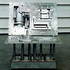
Once the foundry patterns are inspected and verified, they are used to
make multiple aluminum sand castings. The resulting male and female
sand castings are then machined to accurately mount and fasten the
castings to the moldplates. The castings are also drilled and vented so
that there are "vents" evenly covering the surface of the casting. The
venting is important for the molder to fill the cavities with foam beads
and to expand the foam beads with steam during the foam molding process. Other necessary machining operations to the cavities provide locations for fill guns, ejectors, and support posts. The completed and inspected casting sets, or cavities, are then mounted to the mold plates with stainless steel fasteners. Support posts, ejectors, the cooling manifold, and the custom fill plate are produced concurrently with the cavities and available for the final mold assembly. After the final mold assembly the mold is inspected to insure it is in proper alignment and will produce dimensionally acceptable parts. The mold is then crated and shipped to the molder. Here you san see all the pieces that comprise a tool. 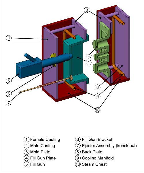
|